The Latest News from Noro USA

From Concept to Operation in Six Weeks: Accelerated Ductwork Installation

We pride ourselves on delivering innovative, cost-effective solutions that drive real-world results for our clients. In this post, we highlight a project where our team was tasked with designing and implementing a custom ducting solution for a thermal oxidizer tie-in  from an oven along  with supply and discharge ducting to the oven cooling zone. Faced with tight deadlines and budget constraints, our integrated approach—combining visual design tools, precise planning, and streamlined installation—enabled the client to go from initial concept to full system operation in just under six weeks.

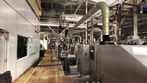
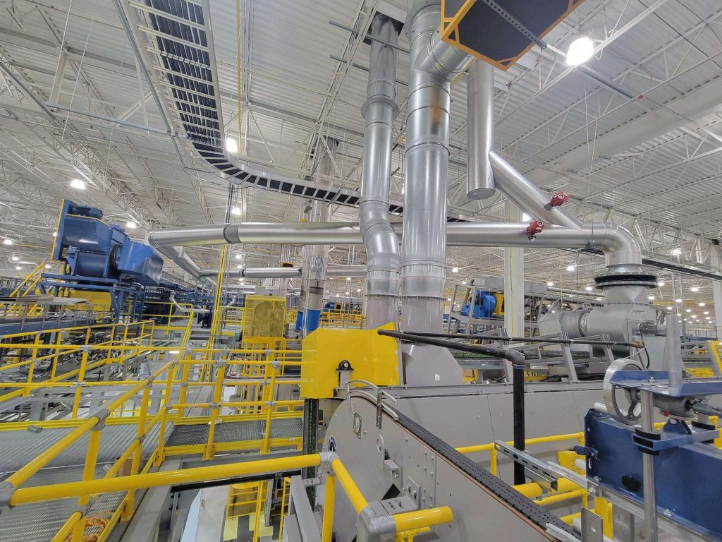
INITIAL DESIGN SUPERIMPOSED OVER THE PROCESS IMAGE

After obtaining the process area image, we designed the ducting system and over-layed the design on top of the image of the process area.  This process allowed plant operations personnel to review the layout and suggest modifications to the design.

Scanned factory image with duct system overlay
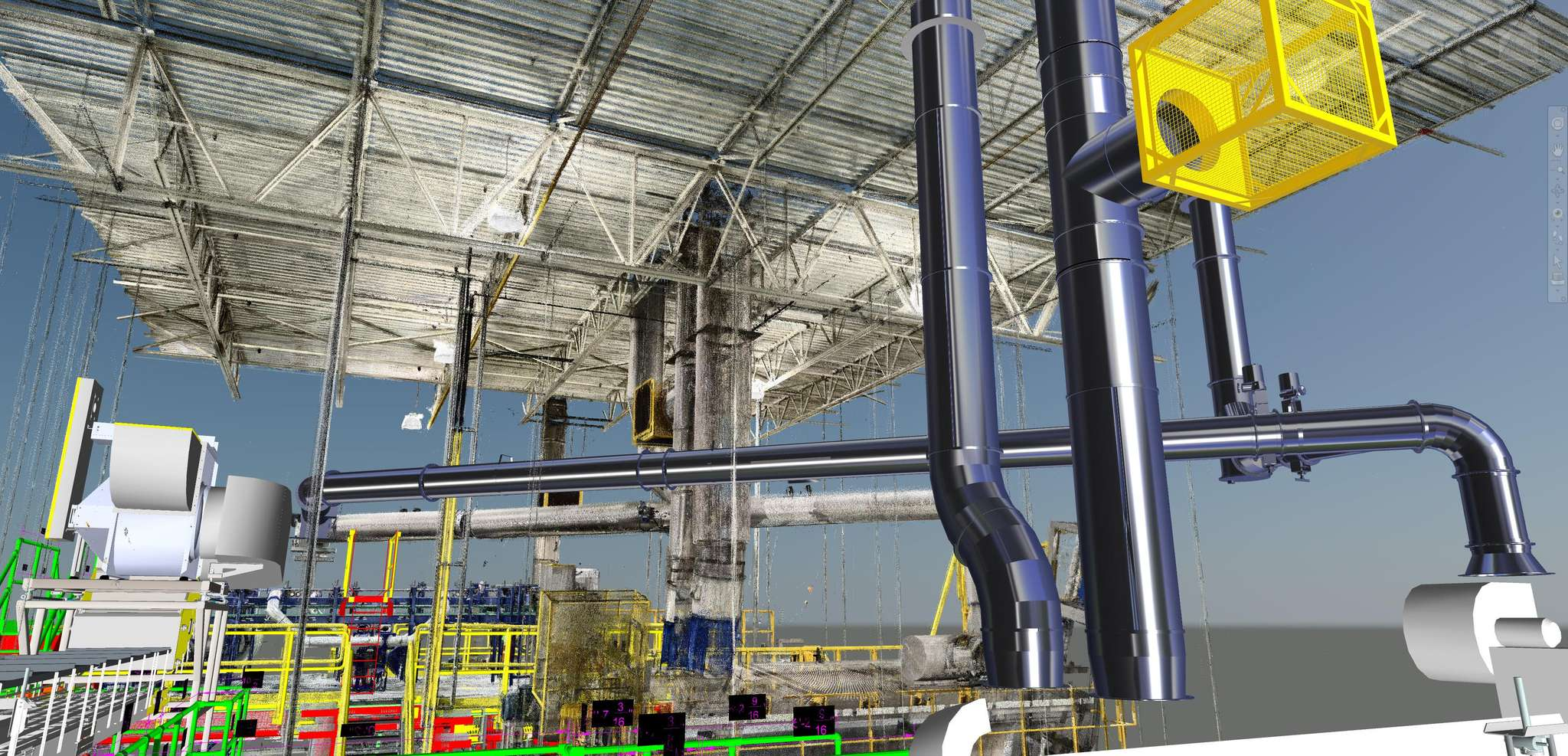
  • The proposed system design and rendering allowed the end user to envision the installed system.
  • This process ensured accuracy in the system quote because the precise part requirements were a part of the design.
  • Our process could be used with any duct type – Euro-style (Noro) tubing, clamp-together rolled-lip duct, flanged ducting, or spiral duct.

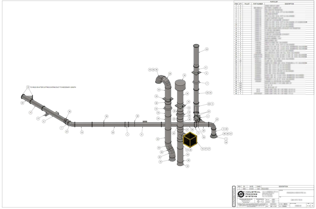
ACCURATE ASSEMBLY DRAWING PRODUCED

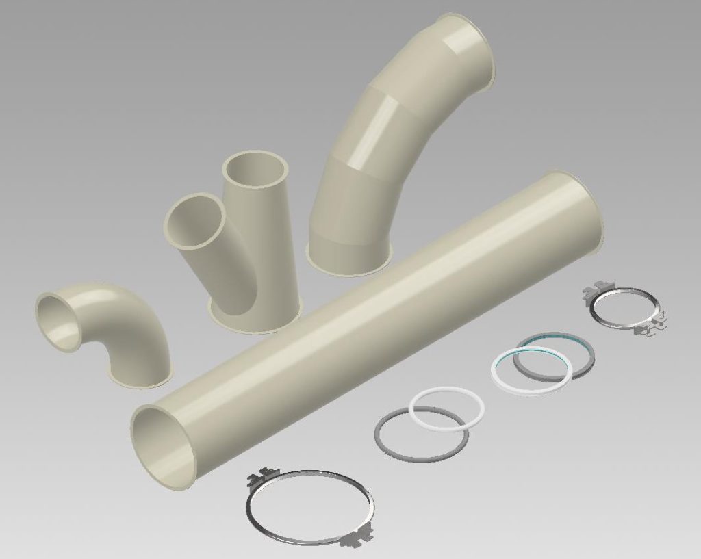
Each part that is required for installation was called out on the assembly plan.  This project included clamp-together duct, flanged duct, expansion joints, automatic butterfly valves, a fabricated air filter, roof curb caps, duct hangers and support collars, duct gaskets, and hardware.

  • All parts were listed on the drawing bill of materials (BOM) and all parts were delivered in a kit to the job site.
  • Delivery to the job site was consolidated into one shipment in order to eliminate the task of the contractor searching for parts.
  • We published easy-to-follow, detailed assembly drawings that expedited the installation of the system.

DETAILED DESIGN PROCESS YIELDED OPTIMIZED RESULTS

In the end, the results of this project were noteworthy. 

  • No installation errors or contractor questions; this system was installed and in-operation before the client project engineer was even aware of it.
  • There were no interferences from the ductwork with joists on roof stack penetrations
  • The installation and system startup was completed in less than a week
  • There was no wasted additional parts (just-in-case) that were shipped to the job site, only to be thrown away after system installation.
  • There was no need for  last-minute rush parts that needed to be shipped to the job site.
  • The result was a total time of six (6) weeks from design start, through component fabrication, to fully installed system, startup, and into operation.

We’ve applied state-of-the-art technology to the process of designing, fabricating, and installing industrial ductwork systems. Using our process will enhance your up-front customer engagement, optimize your quote accuracy, expand your project capabilities, and increase your system sales.

Building a Mist Collection System on Another Continent (Remotely)

In today’s rapidly evolving industrial landscape, efficiency and accuracy are paramount. A technology that has emerged as a game-changer in factory design is 3D imaging. This cutting-edge technology allows for precise details of factory spaces, revolutionizing how equipment layout is conceived and executed.

We recently were asked to provide leak-free ducting on a mist collection system for an industrial process in eastern Europe.  Our customer had a 3D image of the production process and provided these image files to us via an upload to our Nextcloud server.  What follows is a discussion of our experience designing this system and arranging the equipment, along with some comments about the numerous advantages of using 3D imaging technology.

Mist collection duct superimposed over factory image.

Background

An eastern European company has been manufacturing their product for many years in their existing facility.  Due to recent customer requirements, the company recognized an opportunity to alter their product which would result in increased sales.  However, this change would require that a mist collection system would need to be installed on their existing process.  This mist collector is necessary in order to remove fugitive airborne oil mist which would be generated by the equipment when manufacturing the new product.  So, we were asked to provide a proposed design and layout for this system in their (already crowded) manufacturing process.

Unparalleled Accuracy

The cornerstone of any successful industrial dust or mist collection layout is accuracy. And the traditional methods of taking measurements and making sketches are not only time-consuming, but prone to errors and omissions of the necessary details.  On the other hand, 3D imaging technology captures every detail with accuracies to a quarter-of-an-inch, and this ensures that the equipment and ducting fits correctly into the designated space.  Within a week of receiving our customer’s image files, we were able to provide a design for them that showed the proper location for the mist collector, and also showed all the routing of the ducting, imbedded into the image file.  The photos and videos included here show this system superimposed on top of the factory image.

One of the biggest challenges in factory design is ensuring that the new design does not interfere with existing equipment and other infrastructure elements (structural beams, electrical components, etc.)  Our process allows us to avoid these interferences by overlaying the proposed design onto the existing space – in effect, building the system virtually.  This technique resolves all of these of potential interferences long before installation, ultimately minimizing costly rework.  The results translate into accurate accounting for all of the equipment design and part requirements, faster project execution, and shorter installation times, ultimately saving both time and resources.

Enhanced Design Flexibility and Cost-Effectiveness

By designing with 3D imaging, we had the ability to experiment with various locations of the mist collector and routing of the ductwork in a virtual environment. This flexibility allowed us the ability to review different layouts with engineers and plant personnel, and it allows for optimal use of space long before the installation of the system.  The ability to collaborate on these design projects from remote locations is invaluable, and our process facilitates seamless communication between our team and our customers, eliminating the need for physical presence at the site.

Conclusion

We will probably never visit this factory or see the results of this installation in person.  In fact, we really have no idea exactly where this factory is located.  Yet, we were able to design a system that precisely meets the needs of the customer and their production process.  And, we are sure that there will be no last-minute additional parts required, and no rush shipments to the site during installation.

In conclusion, the system that we have developed is a transformative tool in our business.  Its accuracy, efficient information capture, cost-effectiveness, and numerous other advantages make it a real asset for our customers and suppliers alike.  We embraced this technology in order to allow us to create more efficient and more cost-effective layouts, enabling us to excel in industrial environmental design.

Mist Collection Systems: Eliminating Overhead Duct Leaks

Years ago, we learned our lesson on overhead duct leaks. 

The most popular U.S.-manufactured solution for mist collection ducting systems utilizes rolled-end duct. For oil, mist, and coolant collection, that’s a potential problem.

One day, we received a phone call from an overseas factory. They had installed rolled-end duct on a mist collection system to capture machine lubricant mist, and the overhead duct was dripping on workers and equipment. 

Rolled-edge ducts create headaches for mist system installers and users.

The issue: With mist collection duct, every clamp connection – every pipe and fitting – needs a gasket to prevent leaks.

And at this factory, we discovered that the contractor had not installed the gaskets properly. 

Proper installation may have been nearly impossible. The gaskets that were supplied were very difficult to install on large-diameter duct. And, when installing gaskets on overhead duct, you may be working on a 30-foot lift, trying to hold the gasket in place while installing the clamp, without moving any part of the gasket. 

While the gasket can be secured with adhesive or silicon, that’s less than ideal; if the duct is oily, the adhesive won’t hold, and, with silicone, it makes the duct difficult to disassemble. 

Consequently, with rolled-end ducting, each clamp creates a potential point of leakage. The gasket is difficult to install, which raises the chances of a leak.

And as already admitted by the manufacturers, the rolled end connections leak air. So, liquids will find their way out of the connections. 

A Better Design for Mist Collection Ducting

Mist and lubricant collection systems require a different duct design to eliminate dripping, and protect workers and equipment. 

Our Noro duct product line features a flat flange end. The gasket is grooved, which allows it to stay in place over the flat flange. Everything is much easier to assemble.  And, with flat flange clamped to flat flange, with a gasket sandwiched in the middle, you have a perfectly sealed connection.

20221227_110320

 Advantages of Noro tubing:

  • Solidly Connected – Noro duct does not leak air, and the flat flange ends prevent fluid leaks.
  • Energy Efficient – Noro tubing is the most energy-efficient ducting available on the market today.
  • More Robust – The material is 50% thicker than the typical U.S. manufacturer’s duct, allowing for longer span lengths and ensuring years of dependable operation.
  • Better Looking – Powder-coated metal improves aesthetics and ensures durability. 
  • A Wider Range of Applications – With an airtight design, Noro tubing can be used for both pressure (pneumatic conveying) and vacuum (environmental control) systems.

Oil, lubricant, and mist collection systems are essential processes in an operation, and each system must be robustly designed and precisely installed. Noro tubing is simply the most effective choice for these applications.

3D Digital Designs for Easy Installation

To further simplify installation, we can design your system digitally. With a short visit to your facility, we create a three-dimensional image of your process, noting the location of equipment, working paths, and any special considerations. 

From there, our systems design is completed offsite. Our clients are actively involved in the design, and make modifications and improvements before the system is ordered. 

When the system arrives on-site, it’s complete and ready for a hassle-free installation. Overages and underages are minimized, and contractors don’t need to wait for last-minute additional parts to start constructing. 

Our approach reduces costs, improves operational results, and eliminates cost escalation due to change orders from contractors. To learn more about our mist system ducting  –  send us a message.

For Ordering Information Contact Us.


Our Products

System Design